
Engineering
Engineering SLS Prototypes & Parts
Prototyping with 3D printing eliminates the need for molds and tooling, resulting in reduced costs and shorter turnaround times. No molds or tooling allow you to easily make last-minute design changes before printing.
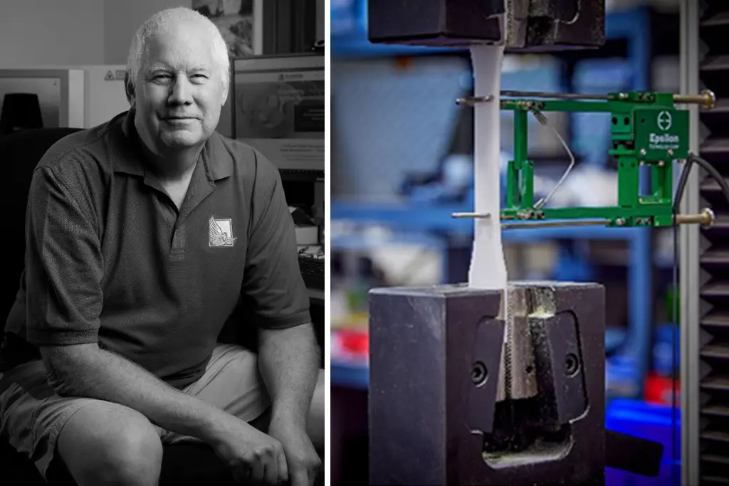
Although we’re typically more affordable, please don’t assume our prototypes and parts are of lower quality; they certainly aren’t. We print prototypes and parts of the highest quality, performance, and function, offering features that are nearly impossible to find in traditional manufacturing. What’s our secret? Yeah, alright, we’ll tell you. It’s our SLS process! Its efficiencies result in reduced costs compared to traditional manufacturing, and those cost savings are all yours. We want to help you succeed with your prototype so much that we’ve even written From Idea to Prototype to help.
Core SLS Features
Why Do We Engineer for SLS?
NW Rapid can create multiple iterations of a part or different versions of a specific design feature simultaneously in the same build. Then, you can evaluate each version for its merit. SLS will produce a robust, high-performance version of your final design. This “final design” can incorporate multiple iterations, with individual labeling or key features that vary from part to part. Without molds and tooling, you can easily make those last-minute design changes before printing!
SLS Design Flexibility Process
The personalization or process flexibility comes at no extra cost to you, unlike other manufacturing methods. This flexible process, coupled with our tough nylon SLS materials, means your prototype and, eventually, your manufactured parts are ready to go straight from our machines to doing work for you. Ask us about engineering your project for SLS—let’s turn your idea into reality!
SLS Simply Affordable Quality
NW Rapid prints parts of the highest quality, performance, and function; sometimes, we can offer features that are nearly impossible to find in traditional manufacturing. Eliminating molds and tooling typically reduces cost and turnaround time. Although we’re more affordable, please don’t think our prototypes are of lower quality—they certainly aren’t!
How Fast and Affordable Are We Talking?
The volume of the 3D model and the overall size of the build determine the turnaround time and price. So, as much as we’d like to give you a number (7?), as with most things, it depends.
Engineering The SLS Process
Create Your CAD File
Once you have established your goal and created the CAD file, upload the file along with your requirements using our Quote Form.
Engineering Consultation
Our engineers will review and discuss the updates as needed for your project. Once the file is approved, our engineers will slice the file into layers 0.10-0.15mm thick and upload it to the SLS printer.
SLS Printing
Layer by layer, our machines build at a rate of approximately 10-15 mm per hour.
SLS Finishing
Once the powder has cooled, a technician removes the part(s) and bead blasts it to remove excess powder. It then moves on to the final finishing.
Specifications
Meet the Builders: Gretel, Hansel, and The Wicked Witch
Expert Guidance
Our Three Performers
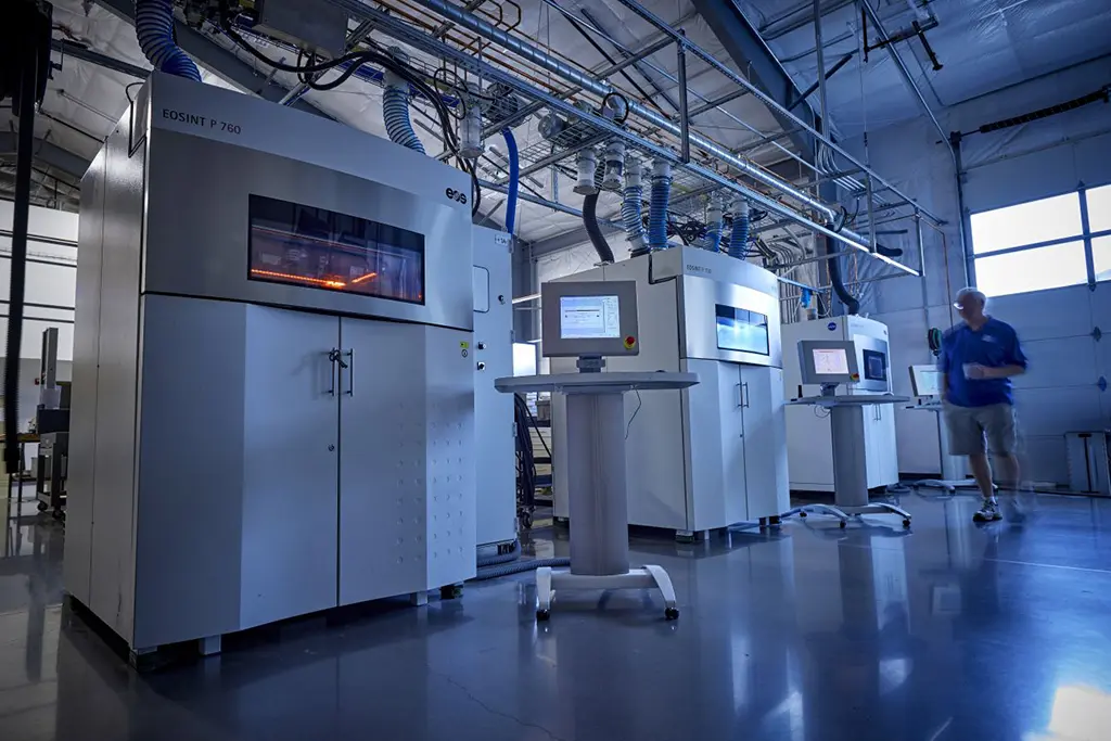
Our Selective Laser Sintering (SLS) machines boast legendary German engineering and the capability to process powders from multiple vendors. Although each has a distinct personality, our SLS machines are all extremely reliable, running thousands of hours with little maintenance.
1Speed times and thickness are material dependent. 2Machine speed during the build process.

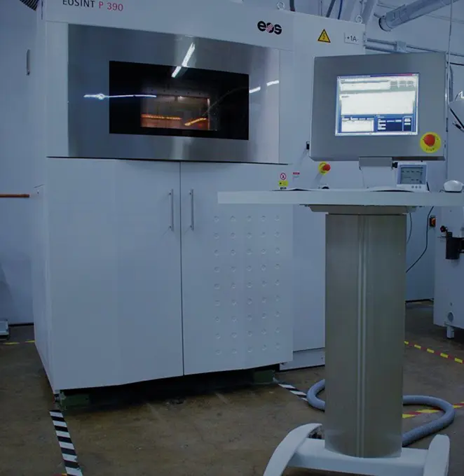
Gretel (aka P390)
A production workhorse that prints functional, high-quality nylon parts. Her smaller build platform allows for quick turnaround times without compromising quality.
- Build Volume: 340x340x620 mm
- Build Speed1: Up to 35 mm height/hour
- Layer Thickness1: 0.1-0.15 mm
- Scan Speed2: Up to 6 m/s

Hansel (aka P730)
One of the largest plastics SLS systems available. Hansel features a double-laser system and a horizontal build, producing the highest part quality and increased productivity, and is well-suited for complex geometries.
- Build Volume: 700x380x580 mm
- Build Speed1: Up to 35 mm height/hour
- Layer Thickness1: 0.12 mm
- Scan Speed2: Up to 2x6 m/s

The Wicked Witch (aka P760)
The newest of our SLS machines is appropriately named The Wicked Witch. Her increased capacity makes her an exceptional choice for serial production and functional prototypes.
- Build Volume: 700x380x580 mm
- Build Speed1: Up to 32 mm height/hour
- Layer Thickness1: 0.06-0.10-0.12-0.15-0.18 mm
- Scan Speed2: Up to 2x6 m/s
SLS Basic Design Guidelines
This guide provides essential information—from SLS material selection and design constraints to file preparation and printing best practices.
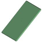
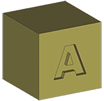 Text — Recessed
- Use a San-serif font, Arial is a good choice
- The font must have Bold applied
- Use a font size no smaller than 16 pt (the larger the better)
- The font depth must be at least 0.8 mm (especially for smaller text - 16 pt); larger text depth can be as shallow as 0.5 mm
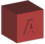 Text — Raised
- Use a San-serif font, Arial is a good choice
- The font must have Bold applied
- Use a font size no smaller than 14 pt (the larger the better)
- The font depth must be at least 0.6 mm
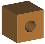 Holes
Holes
- Vertical build orientation—at least 1.5 mm in diameter
- Horizontal build orientation—at least 2.0 mm in diameter
- To maximize resolution, build the part with the holes in vertical orientation and minimize part thickness in that area
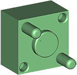
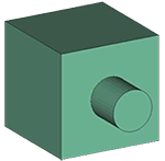 Pins
Pins
- Minimum 1.0 mm diameter
- Either vertical or horizontal build orientation
- Required clearances for movable pins (including hinge pins):
- Minimum 0.3 mm per side (X-Y build)
- Minimum 0.5 mm per side (Z build) (manage this with a hole and/or pin diameter change)
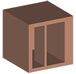
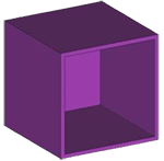 Thin Walls
- Our guaranteed minimum wall thickness for SLS is 1.0 mm (0.04 inches); anything less will be “best effort”
- Minimum wall thickness of 1.5 mm (0.06 inches) for reproducible measurements and mechanical properties
- Orient thin walls for plane-by-plane building to improve accuracy and resolvability
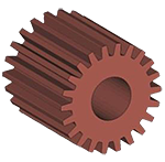 Gears
Gears
- Increase the shaft clearance to 1.0 mm (for free-spinning gears)
- Increase the tooth separation distance to between 0.5 mm and 1.0 mm
- NOTE: You should make any changes to the model before the creating the STL file
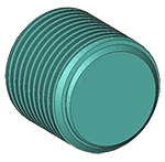 Threads
- Increase the thread clearance by a minimum of 0.1 mm (for printed threads)
- Have the threads added in a post-op process
- NOTE: You should make any changes to the model before the creating the STL file
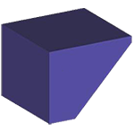 Feathered Edges
- Feathered or knife edges should taper to no less than 0.8 mm (0.03 inches)
- DO NOT taper to a sharp edge (a sharp edge is fragile and easy to break)
 Large Flat Parts
- Large flat parts will warp—the amount of warping depends on the wall thickness, surrounding features, and overall part size
- Use a filled material (e.g., carbon-filled) to help minimize warping. Filled materials will not eliminate warping, but they will significantly reduce it
- Create a space frame (grid) around the part(s) that are removed and sanded after receiving—this will not eliminate warping but, will help reduce it
 Bosses
- The outside diameter of the boss should be 2X to 3X the diameter of the insert to provide sufficient strength and minimize hoop shrinkage (shrinkage in the boss sidewall)
- The boss’s height should be equal to the insert’s height—if the boss is too tall, shrinkage may occur below the level of the boss
- Ribs and gussets may be added for increased strength—the thickness of the rib or gusset should be no greater than 60% of the thickness of the boss sidewall thickness
 Wall Thickness
- The ideal wall thickness is between 1.5 mm and 3.0 mm (0.06 inches and 0.12 inches)
- Have a consistent wall thickness, try to keep all walls the same thickness, avoiding extreme wall thickness variations—large blocks of material will cause excess heat and shrinkage, resulting in part deformation
- Make any internal and/or external ribs, gussets, or baffles no thicker than 60% of their adjoining wall thickness
 Parts with Tight Tolerances
- Our standard production tolerances (with no post-op machining processes) are:
- +/-0.25 mm (+/-0.010 inches) for features less than or equal to 50 mm in size
- +/-0.38 mm (+/-0.015 inches) for features greater than 50 mm in size but less than or equal to 75 mm in size
- For features that are greater than 75 mm in size, our tolerance is:
- +/-0.38 mm plus 0.05 mm per every 25 mm over 75 mm (+/-0.015 plus 0.002 inches per inch for each inch over 3.00 inches)
- Send a print and your RFQ highlighting the desired critical features and feature tolerances
- For the SLS process, it is only possible to build with symmetric tolerances
- For large quantity runs or large parts (with extreme tolerance requirements), leave extra material on the part that can be removed through a post-op machining process
- For small quantity runs (10 or fewer), send the CAD file (in a 3D CAD neutral format) along with your purchase request. This will allow us to adjust the model to account for variations in shrink rates
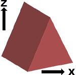 Build Orientation
- Our standard is to build all parts with the shortest side in the “Z” orientation
- If a particular build orientation is required, send a print along with your RFQ highlighting the desired “X-Y-Z” build orientation (be sure to specify the “Z” growth direction)
 Layer Lines
- Since all parts are built layer by layer, angled and curved surfaces may have visible layer lines
- Build orientation can help minimize the visual appearance of layer lines. For a smoother surface, request that the surface be printed (down) for build orientation
- Print the surface at 0 degrees (horizontal) or greater than 20 degrees
- The post-op process of tumbling and/or sanding can be used to smooth out layer lines
 Living Hinge
- Avoid using a living hinge in SLS if possible
- The best material for a living hinge is Nylon 11 (PA850-BLK)
- The hinge should have a minimum thickness of 0.8 mm (0.03 inches)
- NOTE: This is below our minimum guaranteed build thickness of 1 mm (0.04 inches), so this feature will be “best effort”
- Anneal the hinge before flexing—soak the part in boiling water for 10 minutes, then allow the part to cool slowly
- NOTE: This could cause deformation and/or dimensional changes to other features on your part
- Things to NOTE:
- The hinge will flex, but do not expect it to flex like an injection molded hinge
- The hinge will only flex a few times before breaking
- If over-flexed, the hinge will break
- The longer you can make the hinge, the better your chance of success
Download the SLS Basic Design Guidelines PDF
For details specific to your project, it’s best to call us at +1 (503) 434-8557 or request a quote.
Contact Support